Description
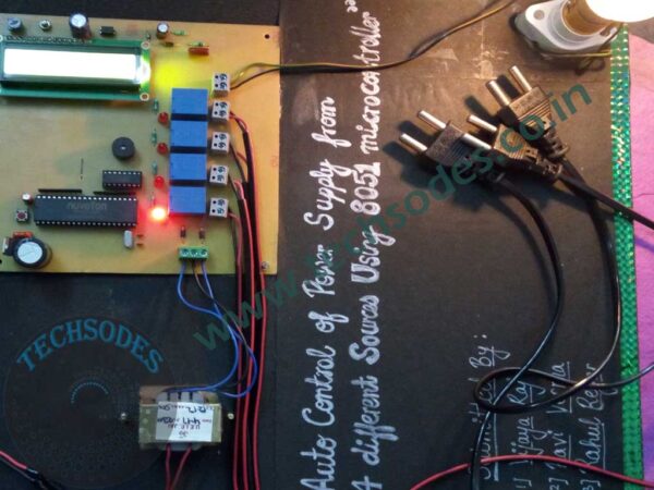
Auto Control of Power Supply from 4 Different Sources Using AT89S52 Microcontroller
Abstract
This project presents the design and implementation of an intelligent, automatic power switching system that can manage and select between four different power sources ? Solar Power, Wind Power, Inverter Power, and Grid Power ? using an AT89S52 microcontroller. The system is designed to ensure that a connected load (represented by a bulb in this prototype) always receives power from the most readily available source, automatically detecting the presence or absence of power in each line and switching accordingly.
In regions where power outages are frequent or where renewable sources are integrated into domestic or industrial systems, such an automatic source management system is critical. It ensures uninterrupted power supply and optimizes the usage of alternative and renewable energy sources before resorting to grid electricity.
The system uses opto-isolators (PC817) for voltage detection, ULN2003A for relay driver control, and relays for switching between power sources. The status of the system is displayed in real time using a 16×2 LCD, and alerts or transitions are indicated using a buzzer.
Introduction
Electricity is a crucial resource for modern life. However, many areas suffer from unreliable power supply due to infrastructure issues or natural constraints. In such areas, it is common to use backup power systems like solar panels, wind turbines, or inverters in addition to the main grid supply. But manually switching between these sources can be inconvenient and inefficient. This project provides an automated, microcontroller-based solution to this challenge.
The primary goal is to develop a system that detects availability of power from each of the four sources and automatically connects the load to the first available source based on a priority sequence. The selection process is carried out by the AT89S52 microcontroller, which controls relays via a ULN2003A driver IC and monitors voltage presence using opto-isolators.
System Overview
The system consists of four different power sources:
- Solar Power
- Wind Power
- Inverter Power
- Grid Power
Each of these sources is connected to an individual relay via a ULN2003A relay driver, which is in turn controlled by the microcontroller. The presence of voltage on each line is detected using PC817 opto-isolators, which ensure complete electrical isolation between the AC mains and the low-voltage logic circuitry. When the microcontroller detects the presence of voltage from a specific line, it activates the corresponding relay, allowing power to flow through to the load holder, where a bulb lights up as an indicator of power flow.
If the selected power source fails, the system automatically scans the remaining sources in order of priority and switches the load to the next available source.
Components Used
| Component | Description |
|---|---|
| AT89S52 | Main microcontroller unit (8051-based) |
| ULN2003A | Relay driver IC to control multiple relays |
| PC817 | Opto-isolators for voltage detection and input isolation |
| Relays (4) | Electromechanical relays to switch each power source |
| 16×2 LCD | Display unit for showing active power source and system info |
| Buzzer | Provides audio alerts for status changes |
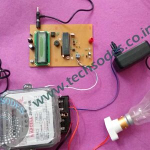
| Load Holder | Socket to hold and power an indicator bulb |
| Bulb | Represents the connected load for demonstration |
| Power Supply | Provides regulated DC supply for the circuit components |
Working Principle
1. Power Detection Using Opto-Isolators
Each power source is connected to a PC817 opto-isolator. When voltage is present on a line, the internal LED of the PC817 is activated, which in turn triggers its internal phototransistor, sending a digital signal to the microcontroller. This allows the MCU to detect which power sources are available, all while ensuring electrical isolation from the high-voltage lines.
2. Relay Switching via ULN2003A
The AT89S52 microcontroller does not have the current-driving capability to operate relays directly. To solve this, a ULN2003A IC is used. It acts as a relay driver, converting microcontroller-level logic outputs into higher-current outputs suitable for relay coil activation.
Each output of the ULN2003A is connected to a relay that corresponds to one of the four power sources. The MCU activates the output pin of the ULN2003A based on which source is available.
3. Load Connection and Switching
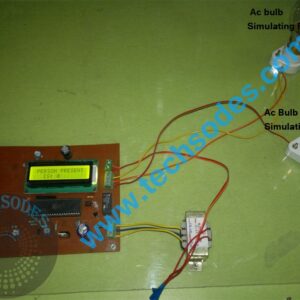
The output side of each relay is connected to a common load line that leads to a holder socket with a light bulb. When the relay corresponding to an active source is turned on, power flows through the relay into the load, lighting up the bulb. The relay connections ensure only one source is connected to the load at a time.
4. Source Priority and Switching Logic
The system follows a priority-based algorithm. For example:
- Solar Power
- Wind Power
- Inverter Power
- Grid Power
The microcontroller continuously monitors the input lines. If multiple sources are available, it selects the one with the highest priority. If the currently active source fails, it immediately scans for the next available source and switches the relay accordingly. This ensures uninterrupted power to the load.
5. Display and Alert Mechanism
A 16×2 LCD displays the current active source, system status, and alerts. For instance, it can show messages like:
- “Solar Power Active”
- “Switching to Inverter”
- “No Power Available”
A buzzer is used to alert users when a transition occurs or if no source is available. It provides a quick, audible indicator of system status.
Features
- Automatic Source Detection using opto-isolated inputs
- Priority-based Source Switching logic
- Relay Control via ULN2003A
- Real-time LCD Display of power source status
- Audio Alert via buzzer for transitions and faults
- Microcontroller-based Logic Control
- Failsafe Operation during power interruptions
- Electrical Isolation between high and low voltage sections
Advantages
- Automation: Eliminates need for manual source switching
- Efficiency: Optimally uses renewable sources like solar and wind before switching to grid
- Reliability: Ensures uninterrupted power supply to load
- Safety: Complete electrical isolation protects the control system
- Scalability: Can be adapted for more or fewer power sources
- Cost-Effective: Uses affordable components and a simple logic
Applications
- Smart Homes with solar panels and backup power
- Rural Electrification Projects where grid power is unreliable
- Industrial Automation Systems needing redundant power
- Telecom Towers with solar, wind, and grid backups
- Educational Demonstrations for power management and embedded systems
Future Scope
- Wireless Monitoring using GSM or Wi-Fi modules
- IoT Integration for remote control and data logging
- Mobile App Control for source selection and status updates
- Real-Time Clock (RTC) to schedule source switching
- Power Quality Monitoring (voltage, frequency, current)
- Battery Charging Control integration with solar or wind sources
- Overload and Fault Protection
Conclusion
The Auto Control of Power Supply from 4 Different Sources project is a powerful demonstration of how embedded systems can provide intelligent control in energy management. With increasing reliance on renewable energy and the necessity of power reliability in both urban and rural settings, this system offers a practical and effective solution.
By using the AT89S52 microcontroller, along with ULN2003A relay drivers, PC817 opto-isolators, and relays, the system achieves full automation of power source selection. The inclusion of LCD display and buzzer makes the system user-friendly and interactive.
This project not only ensures uninterrupted power supply but also optimizes the usage of available power sources, especially renewable ones. It can be implemented in homes, offices, and small industries, and it serves as a solid base for future energy automation systems.


Reviews
There are no reviews yet.