Description
Automatic Power Factor Correction Using AT89S52 Microcontroller
Abstract
This project presents the development and implementation of an Automatic Power Factor Correction (APFC) system using an AT89S52 microcontroller, aimed at improving power efficiency and reducing losses in AC electrical systems. In conventional AC power systems, inductive loads such as fans, motors, and tube lights cause the power factor to drop below unity, leading to inefficient power usage, higher electricity bills, and increased load on the power generation and transmission infrastructure. This project solves the problem by detecting the real-time power factor of the load and automatically switching capacitor banks using relays to compensate for the reactive power and bring the power factor close to unity.
The system uses current sensing, zero crossing detection, microcontroller-based decision-making, and real-time LCD display to offer a complete embedded solution for small-scale power factor correction applications.
Introduction
The power factor is a measure of how effectively electrical power is being converted into useful work output. A poor power factor indicates inefficient utilization of electrical power. In many residential, commercial, and industrial applications, reactive components in the load cause the power factor to lag, which results in increased apparent power (kVA) consumption and penalties in commercial setups.
The Automatic Power Factor Correction System presented here is a low-cost, efficient, and automated solution that improves the power factor by dynamically connecting/disconnecting capacitors in parallel with the load as per the real-time requirement. This system is particularly useful in environments where the nature of the load keeps changing frequently.
System Overview
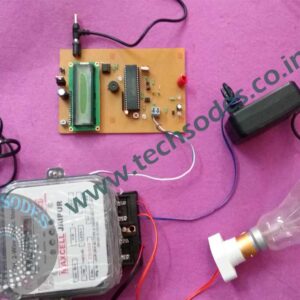
The core of this project is based on the AT89S52, an 8051-based microcontroller from Atmel. It processes the input from the current sensing circuit and timing signals to determine the phase angle between voltage and current. Based on this phase difference, the microcontroller calculates the power factor and decides whether a capacitor needs to be added or removed from the circuit.
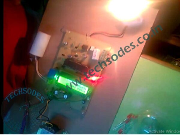
The measured power factor and other operational status are continuously displayed on a 16×2 LCD, allowing the user to monitor system performance in real-time. The correction process is fully automatic, and it responds dynamically to any changes in the load.
Working Principle
1. Current Sensing Circuit:
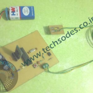
A 1-ohm, 5W resistor is placed in series with the load to sense the AC current. The voltage across this resistor is directly proportional to the current flowing through the load. To isolate the high-voltage AC line from the low-voltage microcontroller circuit, this current is fed into an MCT2E opto-isolator, providing both safety and noise immunity.
2. Zero Crossing Detection and Pulse Generation:
A 555 Timer IC is configured in monostable mode and used in conjunction with the current sensing signal to generate a clean and accurate pulse that is triggered at the zero crossing point of the AC waveform. This pulse is fed into the microcontroller as a reference signal.
3. Phase Angle Measurement:
The microcontroller detects the phase difference between voltage and current waveforms using the timing of the pulse received from the 555 timer. By measuring the time delay between the zero crossing of the voltage and current signals, the microcontroller calculates the power factor angle.
4. Capacitor Switching Using Relays:
Once the power factor is calculated, the microcontroller determines whether additional capacitor banks need to be connected to improve it. If the power factor is lagging (i.e., the current lags behind the voltage), the microcontroller activates the relay to connect one or more capacitors in parallel with the load. This reactive power compensation improves the power factor automatically.
5. Real-Time Display and Load Response:
The entire status ? including load condition, power factor value, and capacitor status ? is displayed on the 16×2 LCD. When the load is changed (e.g., by plugging in different appliances into a holder socket connected to the main line), the system automatically recalculates the power factor and responds by adjusting the capacitor connection. This makes the correction process real-time and adaptive.
Key Components
| Component | Description |
|---|---|
| AT89S52 | Microcontroller (8051 architecture) ? main control unit |
| 555 Timer IC | Monostable pulse generation for timing and ZCD |
| MCT2E | Opto-isolator for current signal isolation and detection |
| 1-ohm 5W Resistor | Used to sense current across the load |
| Relay Module | Electromechanical switches to add/remove capacitors |
| Capacitors | Power factor correction elements |
| 16×2 LCD | Display for real-time monitoring |
| Load Holder | Socket for varying load to test correction functionality |
Features
- Automatic Power Factor Correction based on real-time load changes
- Microcontroller-based design for intelligent decision-making
- Electrically isolated current sensing using opto-couplers
- Real-time LCD Display for PF value, capacitor status, and system state
- Dynamic capacitor switching using relay modules
- Load detection via hardware interface for household appliances
- Low-cost implementation suitable for domestic or educational purposes
Advantages
- Improved Power Efficiency: Reduces reactive power, hence lowering electricity bills
- Automatic Operation: No manual intervention needed
- Safe and Isolated Design: Opto-isolators protect low-voltage circuitry
- Real-Time Feedback: Users can see how the system behaves with different loads
- Educational Value: Demonstrates fundamental electrical engineering concepts
- Expandable: Can be extended to multi-phase systems with higher MCU capacity
Applications
- Domestic households where reactive loads like fans and motors are common
- Small industrial units with dynamic machinery
- Educational laboratories for demonstration of power factor and correction techniques
- Commercial establishments to avoid penalties due to poor power factor
- Street lighting or public utility systems with inductive loads
Future Enhancements
- Digital Power Factor Meter integration for more accurate readings
- Wireless Monitoring using GSM or IoT modules
- Multi-stage capacitor banks for more refined correction
- Overvoltage and Undervoltage Protection
- Use of Solid-State Relays (SSR) for faster switching
- Integration with billing systems for demand-side energy management
Block Diagram (Described Textually)
[Main AC Line]
      |
      v
[Load Holder] --> [1-ohm Resistor] --> [MCT2E] --> [555 Timer] --> [AT89S52 MCU]
                                                          |
                                               [Relay Control Output]
                                                          |
                                               [Capacitor Banks] --> [Main Line]
                                                          |
                                                  [16x2 LCD Display]
Conclusion
This Automatic Power Factor Correction System using AT89S52 microcontroller is a compact, practical, and intelligent solution to the age-old problem of low power factor in AC power systems. By using a combination of analog sensing, electrical isolation, and digital logic, the system automatically compensates for inductive loads using capacitor switching and maintains an optimal power factor near unity. The project demonstrates the successful integration of basic electrical principles and embedded control systems to develop a useful energy-saving solution.
Its simplicity, low cost, and scalability make it ideal for home use, educational demonstrations, and small-scale industrial deployment. The use of real-time feedback, adaptive response to varying loads, and safety through opto-isolation all contribute to making this a robust and innovative embedded solution.