Description
Single Phase Induction Motor Speed Control Using 8051 by DIAC-TRIAC
Abstract
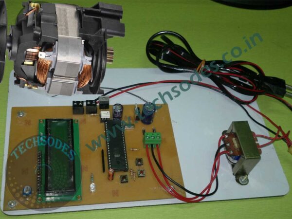
This project focuses on the speed control of a single-phase induction motor using an 8051 microcontroller, DIAC, and TRIAC. Induction motors are widely used in industrial and domestic applications due to their robustness and low cost. However, precise control of their speed is often a challenge, especially in low-cost applications. This project provides a simple and economical method for speed control by using zero voltage switching (ZVS) and phase angle control techniques. The user can increase or decrease the motor speed using two push buttons. A 16×2 LCD is used to display the speed level, and the whole system is powered through a step-down transformer and regulated using a 7805 voltage regulator IC.
Introduction
Induction motors, especially single-phase ones, are commonly found in fans, pumps, compressors, and various household appliances. The speed of an induction motor typically depends on the frequency of the supply voltage, which in most applications is fixed. Therefore, controlling the speed efficiently without changing the frequency is a key area of interest in electronics and automation.
This project demonstrates a simple method of controlling the motor speed using the principle of phase angle control. The phase angle of the AC signal is adjusted using a TRIAC, which is triggered through an opto-isolator and a microcontroller-based control circuit. The 8051 microcontroller reads inputs from push buttons and accordingly changes the firing angle of the TRIAC, which in turn changes the RMS voltage delivered to the motor, thus varying its speed.
Components Used
- 8051 Microcontroller (AT89S52)
Acts as the brain of the system, taking input from push buttons and controlling TRIAC triggering. - Two Push Buttons
Used to increase or decrease the speed level manually. - 16×2 LCD Display
Displays the current speed level or speed number to the user. - TRIAC (BT136)
Used for switching AC power to the induction motor and controlling the phase angle. - DIAC
Ensures that the TRIAC triggers only after a certain voltage threshold, providing reliable firing. - Opto-isolator (MOC3021)
Provides isolation between the high voltage TRIAC circuit and low voltage microcontroller circuit. - Zero Crossing Detector (ZCD)
Built using an optocoupler or transistor circuit to detect the zero-crossing points of the AC waveform. - 7805 Voltage Regulator
Provides regulated +5V DC power to the microcontroller and LCD. - Bridge Rectifier (using 1N4007 diodes)
Converts AC from the transformer into DC. - 12-0-12V / 500mA Step-down Transformer
Converts 220V AC to 12V AC. - Capacitors and Resistors
Used for filtering, timing, and voltage division. - Single Phase Induction Motor (Up to 1 HP)
The load whose speed is to be controlled.
Working Principle
The speed of a single-phase induction motor can be controlled by varying the amount of voltage supplied to it. In this project, the voltage is varied by changing the firing angle of the TRIAC, which is controlled using the microcontroller and DIAC.
- Zero Crossing Detection (ZCD):
The AC waveform crosses the zero line 100 times per second in a 50Hz system. A zero-crossing detector identifies these points and sends pulses to the microcontroller. These points act as references for triggering the TRIAC. - Phase Angle Control:
Once the zero crossing point is detected, the microcontroller waits for a certain delay (depending on the speed level selected via push buttons), then sends a trigger signal to the MOC3021 opto-isolator. The opto-isolator in turn triggers the TRIAC through the DIAC, which allows current to flow through the motor. - Manual Speed Control:
The user can press the increase speed or decrease speed buttons to change the delay after each zero crossing. A shorter delay means the TRIAC conducts earlier in the AC cycle, resulting in more voltage and higher motor speed. A longer delay reduces the conduction angle, lowering the motor speed. - Display Output:
The current speed level (as a numeric value) is displayed on the LCD. This is not the actual RPM but a user-defined level ranging from 0 (off) to maximum (usually 9 or 10 levels).
Advantages of Using DIAC and TRIAC
- Efficient Power Control:
TRIAC allows bidirectional control of AC power, making it suitable for inductive loads. - Cost-effective:
Avoids the need for expensive motor controllers or inverters. - Optical Isolation:
Using MOC3021 ensures that the microcontroller is protected from high voltage fluctuations. - Reliable Triggering:
DIAC ensures that the TRIAC is triggered at a consistent voltage, improving stability.
Circuit Description
The AC supply is stepped down using a 12-0-12V transformer and rectified using a bridge rectifier. The rectified DC is filtered and regulated using the 7805 voltage regulator to power the 8051 microcontroller and LCD.
A small portion of the AC waveform is used for zero crossing detection. This part of the circuit uses a resistor network and optocoupler to safely detect when the waveform crosses zero. The output of the ZCD is connected to an external interrupt pin of the microcontroller.
The two push buttons are connected to the I/O pins of the microcontroller with internal pull-up resistors enabled. When the user presses a button, the microcontroller adjusts a variable delay used in its TRIAC triggering algorithm.
The microcontroller sends a pulse to the MOC3021 opto-isolator, which is connected in series with a DIAC and TRIAC. When triggered, the TRIAC conducts and allows AC power to pass through the induction motor.
Software (Embedded C Programming)
The code for the 8051 is written in Embedded C using the Keil uVision IDE. The basic logic is:
- Detect zero crossing through external interrupt.
- Introduce a delay depending on speed level.
- Trigger the TRIAC via the opto-isolator.
- Monitor push buttons for user input.
- Update speed level and refresh the LCD.
Sample logic for zero-crossing interrupt:
void external_interrupt() interrupt 0 {
    delay_based_on_speed();
    trigger_TRIAC(); // send pulse to MOC3021
}
Button input handling:
if (button_increase_pressed && speed < max_speed) {
    speed++;
}

if (button_decrease_pressed && speed > 0) {
    speed--;
}
LCD displays:
LCD_Display("Speed Level: ");
LCD_Display_Number(speed);
Safety Measures
- Optical isolation is implemented to protect the microcontroller from mains voltage.
- Fuses and MOVs (Metal Oxide Varistors) can be added for extra protection.
- Ensure proper heat sinks on the TRIAC and opto-isolator if used continuously under load.
Applications
- Ceiling fan speed control
- Domestic water pump control
- Industrial motor speed control (for low-power applications)
- Educational and demonstration purposes
- Any AC motor-based appliance where manual speed variation is needed
Limitations
- This project is suitable only for resistive and low-power inductive loads (up to 1 HP).
- Not suitable for high-precision motor control applications.
- Actual RPM is not measured; only the conduction angle is controlled.
- Requires careful handling of AC power components.
Future Scope
- Implement feedback control using a tachometer to measure actual RPM.
- Add remote control via IR or RF modules.
- Replace buttons with a rotary encoder or capacitive touch panel.
- Control multiple motors with PWM and triac phase control.
- Add Wi-Fi or Bluetooth for IoT integration and mobile control.
Conclusion
This project successfully demonstrates a low-cost and effective method for controlling the speed of a single-phase induction motor using phase angle control via TRIAC and DIAC. By incorporating push buttons and an 8051 microcontroller, users can easily adjust the motor speed manually. The use of ZCD and optical isolation ensures safe and accurate control. This is an ideal solution for educational and small industrial applications where cost and simplicity are key.


Reviews
There are no reviews yet.