

Description
Abstract – Wireless Mobile Charger System ? 5W Model
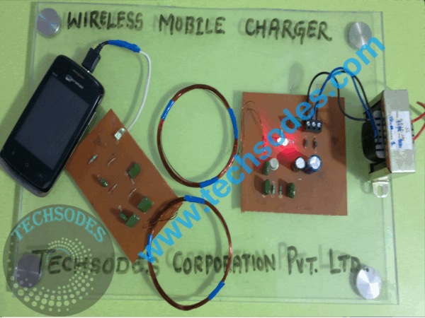
The Wireless Mobile Charger System is designed to charge mobile phone batteries without the need for physical wired connections, using inductive coupling technology. In this system, electrical energy is transferred from a transmitter coil to a receiver coil through an electromagnetic field. The specific model discussed here provides up to 5 watts of charging power, making it suitable for low- to medium-power mobile devices.
The ultimate vision for wireless charging is convenience?eliminating the need for tangled cables and enabling the user to simply place their mobile device on a charging surface. Over time, such systems could standardize power transfer interfaces and automatically adjust settings to accommodate different battery chemistries and capacities.
This project is divided into two functional sections: the transmitter circuit and the receiver circuit. The transmitter converts standard AC mains power into a high-frequency oscillating magnetic field, while the receiver captures this energy and converts it into a regulated DC output suitable for charging a mobile battery.
The 5W charging capacity allows for moderate-speed charging of smartphones, Bluetooth accessories, and other portable devices without significant heat loss or power inefficiency. This makes the system ideal for everyday use in both home and workplace environments.
1. Introduction
Wireless charging has emerged as a popular feature in modern electronics, offering ease of use, safety, and aesthetic benefits. In place of the traditional charging cable, power is transferred using inductive coupling?a method that has been used in applications like electric toothbrushes and biomedical implants for decades.
The main driver for developing this 5W wireless charger is to create a low-cost, reliable, and efficient charging solution for mobile devices without complex infrastructure requirements. It is especially useful for environments where physical connectors are inconvenient, prone to wear, or susceptible to dust and moisture.
2. System Overview
The wireless charging system consists of:
- Transmitter Circuit (Power Source) ? Converts 230V AC mains to high-frequency AC for magnetic field generation.
- Receiver Circuit (Mobile Interface) ? Captures the electromagnetic energy and converts it to stable DC for the phone battery.
Both sides are tuned to work at the same resonant frequency to maximize energy transfer efficiency.
3. Transmitter Circuit Design
3.1 Step-Down Transformer
- A 230V to 12V AC step-down transformer reduces mains voltage to a safer level for circuit operation.
- The transformer is rated to handle the current requirements for 5W output, typically around 0.5?1A on the low-voltage side.
3.2 Rectification Stage
- Uses a bridge rectifier to convert 12V AC to 12V DC.
- Four diodes arranged in a bridge configuration ensure full-wave rectification.
3.3 Filtering Stage
- A 2200?F, 25V electrolytic capacitor smooths the DC output by removing ripples.
3.4 Oscillator Circuit
- Generates a 10MHz oscillating signal to drive the transmitter coil.
- The high frequency is chosen to optimize inductive coupling efficiency for the coil design.
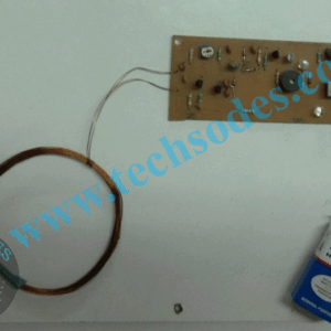
3.5 Transmitting Coil
- A flat spiral coil made of copper wire, tuned for resonance at the operating frequency.
- The coil creates an alternating magnetic field that extends several centimeters from its surface.
4. Receiver Circuit Design
4.1 Receiving Coil
- Placed within close proximity to the transmitter coil for maximum coupling efficiency.
- The magnetic field induces an alternating voltage in this coil.
4.2 Voltage Multiplier Stage
- Consists of a diode-capacitor network to increase the induced voltage to a usable level.
4.3 Rectification and Regulation
- Diodes in the voltage multiplier also act as rectifiers, converting AC to DC.
- An optional voltage regulator can ensure a stable 5V output for USB charging.
4.4 Output to Mobile Battery
- The regulated DC output is connected to the mobile device?s charging input.
- This system delivers up to 5 watts, typically at 5V / 1A.
5. Power Transfer Principle
The charging system uses inductive coupling, which works as follows:
- The transmitter coil, driven by high-frequency AC, generates a time-varying magnetic field.
- The receiver coil, placed within the magnetic field, experiences an induced voltage (Faraday?s Law of Induction).
- This induced voltage is converted into a stable DC supply for charging.
The efficiency depends on:
- Alignment between coils
- Distance between transmitter and receiver
- Frequency tuning for resonance
For this 5W system, the optimal coil separation is typically less than 5 cm.
6. Advantages
- Cable-Free Charging ? Eliminates wear and tear on connectors.
- Safety ? No exposed conductive contacts; reduces electric shock risks.
- Low Cost ? Uses readily available components and simple construction.
- Universal Compatibility ? Can be adapted to various small devices.
- Waterproof Potential ? Ideal for sealed devices since charging ports are not required.
7. Applications
- Mobile Phones ? Convenient everyday charging.
- Bluetooth Devices ? Earbuds, headsets, and speakers.
- Digital Cameras ? Compact camera battery charging.
- Wearable Devices ? Smartwatches and fitness trackers.
- Gaming Accessories ? Controllers and handheld consoles.
- Medical Equipment ? Pacemakers and hearing aids with sealed designs.
- Future Expansion ? Potential for EV charging pads, e-bikes, and power tools.
8. Technical Specifications (5W Model)
| Parameter | Value |
|---|---|
| Input Voltage (AC) | 230V |
| Transformer Output | 12V AC |
| DC Output (Transmitter) | 12V DC |
| Oscillator Frequency | ~10 MHz |
| Output Power | 5W (Max) |
| Charging Output | 5V / 1A |
| Transmission Range | < 5 cm |
9. Limitations
- Short Range ? Effective charging distance is under 5 cm.
- Lower Efficiency ? Typically 60?75% for this type of design.
- Charging Speed ? 5W power is slower compared to modern 15W?30W fast chargers.
- Alignment Sensitivity ? Coils must be well-aligned for efficient charging.
10. Future Enhancements
- Higher Power Output ? Upgrade to 10W or 15W for faster charging.
- Qi Standard Compatibility ? Ensure interoperability with commercial chargers.
- Multi-Device Pads ? Enable simultaneous charging of multiple devices.
- Smart Control Circuits ? Auto power-off when the device is fully charged.
- Magnetic Alignment Systems ? Built-in magnets for automatic coil alignment.
11. Conclusion
The 5W Wireless Mobile Charger System demonstrates how inductive coupling can be implemented with basic components to deliver reliable and safe mobile charging. While it is slower compared to wired fast charging, the convenience of placing a device on a charging pad without plugging in makes it highly appealing for everyday users.
Its low cost, simplicity, and portability make it suitable for personal projects, educational purposes, and small-scale commercial applications. With further refinements in coil design and control circuitry, the system could be adapted for higher power outputs and broader device compatibility.


Reviews
There are no reviews yet.